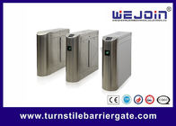
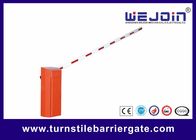
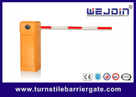
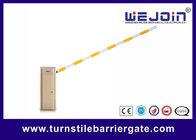
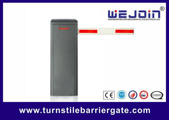
High-Performance and Customizable Car Park Barrier Gate for Parking Facility Security
Automatic Barrier Gate Brief Introduction
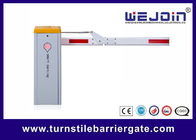
The product consists of four parts: cabinet, transmission mechanism, control unit, and boom. It distinguishes between left-installed and right-installed, and it is used in parking lot entrance and exit control systems.
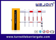
This product is divided into three types: barrier gate with straight boom, barrier gate with folding boom, and barrier gate with fence boom.
Boom Barrier Basic Features
1. Driven by a motor and equipped with a linkage transmission mechanism and a balance spring, it operates stably and reliably. The motor lifespan exceeds 2.5 million times, and the spring lifespan reaches 500,000 times.
2. All models are standard with an obstacle - sensing rebound function. When the barrier arm encounters resistance during the lowering process, it will automatically rebound.
3. It supports external connection of radar, loop detector, and infrared anti - collision functions. With a built - in DC 12V power output, it can supply power to external radar devices.
Type |
Description (Boom Length=L, Meters=M, Seconds=S) |
Barrier gate with straight boom |
L≤3M, up speed 1.5S. L≤4M, up speed 3S. L≤4.5M, up speed 4S. L≤5M, up speed 5S. L≤6M, up speed 6S. |
Barrier Gate Controller Interface
1. Wire Control Interface:
This interface is available for parking system, also available for external controller to control barrier gate.
2. Anti-smashing Interface:
Infrared Photocell: Boom will lift up when short circulate "Infrared photocell" and "GND" interfaces during boom falling down.
Loop Detector: Boom will lift up when short circulate "loop detector" and "GND" interfaces during boom falling down; when boom moves to up limit position, boom will fall down after "loop detector" and "GND" interfaces disconnected.
3. Relay Output Interface:
The relay output can be set to meet different application requirements by setting the output mode. For details, please refer to item H-16 of advanced settings. The default is that the limit signal output is as follows:
When the barrier opens to up limit position, the COM and LmO are connected;
When the barrier closes to down limit position, the COM and LmC are connected;
During the opening and closing, COM and LmC, LmO are disconnected.